Wearable Computing Project (5/10)
Posted by Wesley on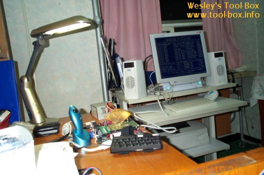
What is missing in this picture? That's right. This computer did not have a dedicated monitor, and had to borrow the monitor from the Portable Athlon. You'll also notice that a Zalman CNPS3100G (review) was sitting on the CPU, which easily exceeded the height limit of 4cm. The particular heatsink was placed there simply because the intended heatsink, Alpha PAL153U, had not arrived yet. This heatsink was only 2.5cm in height, and passed the height requirement. You'll see this heatsink attached on the system later on. Back to the monitor problem, the trouble was that the monitor had to be either directly attached to the system, or had to be worn somehow. Knowing that the former solution wasn't viable due to the uncertainty in how the system was actually going to be worn at this point, I opted for the latter, meaning I had to find a monitor small enough to be worn... on my left arm. So the 'other attachment' was going to be a monitor.
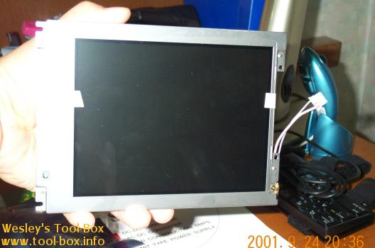
Some product browsing at LG.Philips LCD website revealed that their 6.4" LCD with VGA resolution, LP064V1, was the only model that seemed to meet the size requirements. While VGA resolution of 640x480 does not seem a lot, achieving even this resolution at 6.4" screen size meant that the pixel pitch had to be 0.20mm, which is one of the finest in the industry. Incidentally, this monitor was also intended for industrial application, like the motherboard.
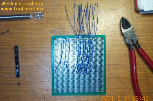
I asked LG.Philips LCD for purchasing information and they directed me to Eunpa LCD, their primary distributor. I visited their office and after some explanation, I was able to get my hands on the said LCD panel. They usually didn't sell these kind of LCD panel to individual user due to their special application. Since the motherboard had a native LCD panel output header, I decided to create a direct link between the LCD panel and the motherboard. Unfortunately, the pin out order was completely different, so I had to make a conversion interface circuit board for translating the pin outs. As you can see in the picture, this was no easy task, involving in interconnecting about a hundred end points on a small breadboard.
Now the main components for the project seemed to have all been gathered. But they were all in their bare forms.