Wearable Computing Project (8/10)


Posing for a magazine photographer while wearing the wearable computer. Photo courtesy of I Love PC.

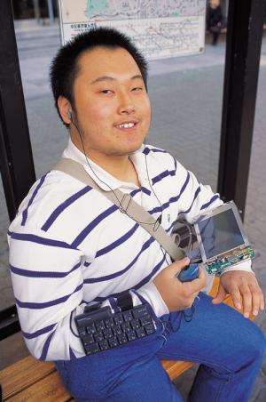
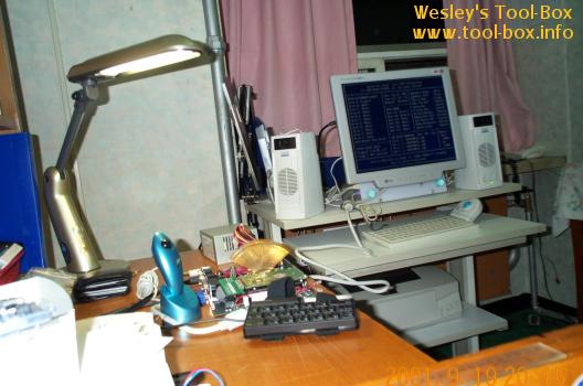
Because 'I Love PC' wanted to have my wearable PC introduced in their next issue (December 2001), I quickly attached leather straps on the monitor and bought a small totebag to put my system in. The above picture is the actual photo that went into print in the said issue of the magazine. This marks my second entry in their 'Computer Freaks' section; first one was, of course, the Portable Athlon, which was shown in the May 2001 issue.

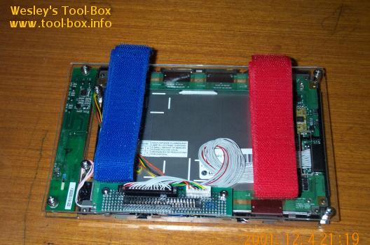
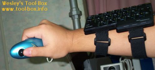
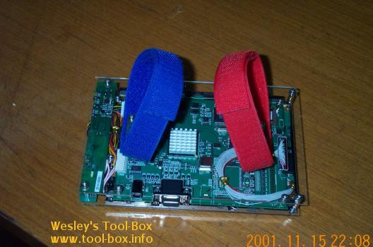
While the quick-fix proved to be stable enough for the duration of the photo shoot, I noticed that some improvements were in order. Most notably, the display was bulky as expected and the leather straps proved to be uncomfortable. I couldn't do anything about the bulky part, as it was mainly attributed to the ADC attached to the back, but I decided to replace the strap with a Velcro type. It proved to be a lot better and reduced weight, slightly alleviating the bulkiness.

Velcro straps on the monitor

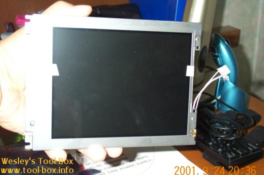
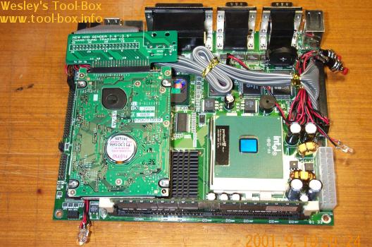
Good news came from Maxan a day after this. They notified me that the BIOS fixing the compatibility issue with my LCD panel had been finished. This meant that I could dump the ADC! I rushed to their office (which had been moved to downtown Seoul, making it easily accessible from subway) and replaced the BIOS chip. They did not have BIOS flashing procedures like some of you are used to, apparently.

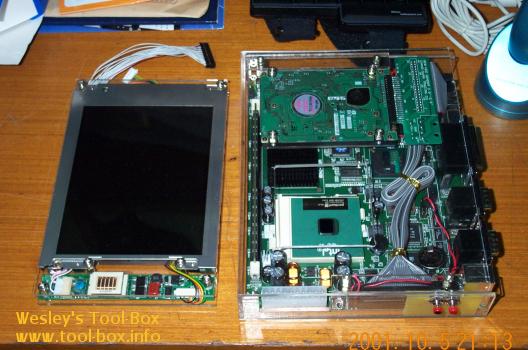
I removed the ADC from the monitor, and attached the conversion interface instead, so the monitor and the motherboard would have a direct digital data link like a laptop. I really liked this, because not only did it reduce the thickness (and thus the bulky look) back to the original design, it reduced weight, increasing comfort level. The thickness of the panel itself is now about 1cm thick.

The LCD monitor without the ADC.

Wearable Computing Project (7/10)


Initial testing of the newly created power supply

Due to the relatively low power requirements of the system as confirmed by an ATX circuit load measurement device I created (shown in the middle between the system and the power supply) the designed maximum of the power supply (3.3V - 20W, 5V - 40W, 12V - 20W) was not strained, as expected. The software controlling of the power worked as designed, and the output power was stable, observing no operational anomalies. In other words, it worked perfectly! Time to integrate it into the system.

The power supply is attached to the cover of the system

At first, the power supply did not operate properly when put into the system. I've isolated the problem to be an unintended short-circuiting created by the hard disk. So I took some extra precaution and applied non-conductive film where the electrical components might touch each other. No problems occurred thereafter, thankfully.

Now that the power supply is in, I needed a battery to operate the system so that I wouldn't need external power when I wear it around. At this point, Mr. Yang, a reporter of I Love PC (yes, that company who lent me a space in the exhibition booth), heard about the project and offered to connect me to a manufacturer that produced auxiliary battery power for laptop computers. My power supply had flexible power input range of 18V~32V, so I had hoped that some of their models would fit into this requirements. I was relieved to learn that they had 19V model of their laptop auxiliary battery, 'MobyPower'. I asked for one, and they provided one for free in exchange for some exposure of their product on a magazine (guess which one?).

The system finally runs independently from a battery; it is running 3DMark2001.

As you can see in the picture, the system was now successfully running off a battery... or so I thought initially. A slight problem was encountered in that, while being heavily stressed, the battery's output voltage decreased to an unacceptable level, far below the 18V, which caused my power supply to halt operation. I decided that the solution to the problem was to use two of their 15V models in serial operation so as to prevent any under-voltage situation. They heartily agreed to provide the two 15V battery packs when I returned the 19V model. This indeed solved the problem completely, and I now had a truly full-operational system. Is this the end? Of course not. Remember it was supposed to be 'worn'?

Wearable Computing Project (6/10)


Clear Acrylic Casing for the Components

As usual, I chose to use the clear acrylic board ('Plexiglas') to house the components. As you can see in the picture, both the monitor and the main system looks quite nice in their casing. Because I now had some experiences with crafting the boards (I took a crafting class this semester) and I got myself a handheld electric drilling machine and some board cutting knives, I needed little help in creating the casing this time around.

Draw your attention on the monitor. It has two unconventional data cable sticking out of it; this is the native 32-pin digital data cable and the 10-pin power line of the LCD panel. These need to go through the conversion interface I've made earlier before being hooked into the motherboard. So I did do that, and boot up the system... and what gives? The LCD panel was going haywire. I had double-checked the interface board so as to not have any misconnections, so I was pretty sure I didn't make a mistake on my part. Therefore, I called the Eunpa and Maxan about this situation. After a bit of digging in, it turned out that the BIOS of the motherboard did not have proper support for my LCD panel yet, and the problem wasn't going to be addressed any time soon.

First successful operation of the whole system

That was rather disheartening, as it meant the simplistic digital connection wouldn't be possible and I had to resort to analog-digital conversion of the video signals. I contacted Eunpa for an Analog-Digital Converter board, I could get it about a week later. Because of the dimensional constraints on the main system, I opted to add the ADC behind the LCD panel. This increased the thickness of the monitor by two times. It wasn't very elegant, but it was the only option I had at the time. But as you can see, at least the LCD panel displayed the screen properly. Finally! I was still annoyed about using the thick analog monitor cable, but I proceeded onto installing Windows 2000 and the whole setup went smooth.

Now came yet another big block in the creation of the wearable. I needed to power the system with a DC voltage input (i.e. battery). Despite the small size of the motherboard, it still used an ATX power connector for its power needs, and I've yet to come across an ATX power supply based on DC input. As you would all know, the casual power supply you can buy are plugged into an AC power outlet, not to mention big. I couldn't move around freely if I needed to plug my system into a power outlet (this is the obvious problem in my Portable Athlon). Also, even the smallest power supply out there, designed for 1U server, was too big to fit into my system. So I needed to tackle a two-fold problem of making a power supply small enough to be housed within the system, while it gets a DC voltage input.

Of course, trying to search for a ready-made product that meets such needs would be futile, and thus I decided to design a power supply of my own. With the electrical knowledge I've learned so far at school, and studying the ATX specification from Intel, I designed a circuit board capable of a single DC input and triple DC output, with the on/off control managed by remote-on pin, as ATX specification pointed out. This feature is necessary for software controlling of the power, e.g. if the operating system was to successfully turn off the system at shutdown. Using some high-efficiency DC-DC converters and some SSC (solid-state relay) I crafted a circuit board that followed my electrical design while conforming to the size constraint imposed in my system casing.

Custom-design ATX power supply

The said size constraint forced me to make the components be laid out in two bread boards, then linked together at different height at the middle. This way, one half of the circuit could come under the hard disk area, avoiding a short-circuit.

Wearable Computing Project (5/10)


Initial testing for well-being of the components attached

What is missing in this picture? That's right. This computer did not have a dedicated monitor, and had to borrow the monitor from the Portable Athlon. You'll also notice that a Zalman CNPS3100G (review) was sitting on the CPU, which easily exceeded the height limit of 4cm. The particular heatsink was placed there simply because the intended heatsink, Alpha PAL153U, had not arrived yet. This heatsink was only 2.5cm in height, and passed the height requirement. You'll see this heatsink attached on the system later on. Back to the monitor problem, the trouble was that the monitor had to be either directly attached to the system, or had to be worn somehow. Knowing that the former solution wasn't viable due to the uncertainty in how the system was actually going to be worn at this point, I opted for the latter, meaning I had to find a monitor small enough to be worn... on my left arm. So the 'other attachment' was going to be a monitor.

The LG.Philips 6.4" LCD Panel in its raw form

Some product browsing at LG.Philips LCD website revealed that their 6.4" LCD with VGA resolution, LP064V1, was the only model that seemed to meet the size requirements. While VGA resolution of 640x480 does not seem a lot, achieving even this resolution at 6.4" screen size meant that the pixel pitch had to be 0.20mm, which is one of the finest in the industry. Incidentally, this monitor was also intended for industrial application, like the motherboard.

I asked LG.Philips LCD for purchasing information and they directed me to Eunpa LCD, their primary distributor. I visited their office and after some explanation, I was able to get my hands on the said LCD panel. They usually didn't sell these kind of LCD panel to individual user due to their special application. Since the motherboard had a native LCD panel output header, I decided to create a direct link between the LCD panel and the motherboard. Unfortunately, the pin out order was completely different, so I had to make a conversion interface circuit board for translating the pin outs. As you can see in the picture, this was no easy task, involving in interconnecting about a hundred end points on a small breadboard.

The tedious creation of an LCD interface

Now the main components for the project seemed to have all been gathered. But they were all in their bare forms.

Wearable Computing Project (4/10)


When the computer is being used while being 'worn', the input devices must be on the user's body in some fashion, as they would not have a solid surface to be placed on like the traditional keyboard and mouse. This departure from the conventional placement of input devices had been immediately on my mind after the motherboard was chosen. Using a mini-keyboard similar to what I have on my portable Athlon deemed too bulky, despite its relative smallness. Those flexible rubber keyboards that you could fold around came up next, but I found the keys very uncomfortable to type, especially while being attached to my body. So I did a search for mobile input devices, and I came across HalfKeyboard from Matias Corporation.

Matias HalfKeyboard Normal Version

It had only half the keys of a traditional keyboard, but because of its unique design, it enables the user to type any key present on a normal keyboard with only one hand. I found this product to be a perfect thing for my project, and despite the hefty price tag of $300, I immediately ordered a wearable version.

Then I needed a pointing device. I vaguely remembered a certain mouse that you could put on a finger to control the cursor, but I couldn't remember its exact name or form, so I gave up and I tried to look for a similar device. Interestingly, Logitech had the solution, with their TrackMan Live! presentation trackball which could be held in one hand to control cursor movements. But the local distributor no longer imported this product due to the extreme unpopularity. I thought I hit a wall at this point, but searching various shopping sites revealed a handheld trackball called 'Little Dolphin' from J&J Magnetic. This one was small enough to be easily fit in one hand (TM Live! seemed tad big for my small Asian hand), and only cost about $12. This was a fine pointing device of choice in a mobile situation, I thought.

J&J Magnetic's Little Dolphin Trackball

I had to wait about a week for the HalfKeyboard to arrive from Canada so I could try on the actual functionality of these devices. The package eventually arrived, and I immediately put them on. It took a bit of time to get used to, but I found my choices of devices to be quite satisfactory for its intended purposes.

Wesley is trying out both of the devices

As you can see, both devices could be worn on one arm, leaving the other arm free for other attachments. I just had to make sure the 'other attachment' did not conflict with the use of the left hand for using the keyboard. Functionality of the input devices being confirmed, I attached a 2.5", 20GB(Model MHN2100AT) Fujitsu hard disk, which would function as the main data storage on the motherboard so I could install an OS (certainly not Windows CE, mind you).

The MSC-740B with the Fujitsu Hard Disk

Notice the IDE cable needed to be shortened a bit to save room. I took care of this part later by buying a custom-ordered IDE cable with proper length. Also, you can see some LED's sticking out at the bottom of the hard disk. These are LAN signal lights. I later removed these mainly because it seemed rather unnecessary. The other LED, to the right of the CPU is the HDD access light, and remained at its place. It was a high-intensity blue LED from Toyoda-Gosei. The buttons at the top right are Power and Reset switches, naturally.

Copyright (C) 1996-2024 Woo-Duk Chung (Wesley Woo-Duk Hwang-Chung). All rights reserved.